| HOME | NORTON | TRIUMPH | LAVERDA | MV AGUSTA | NEED FOR SPEED | NEW ZEALAND RIDES | LINKS | FOR SALE | TECHNICAL ARTICLES |
LINKS
Contact Jim Bush by email Phone 604-535-5800
|
project file: MV AGUSTA 1970's CLASSIC RACE REPLICA with a modern 2004 MV 750cc F4 engine |
|
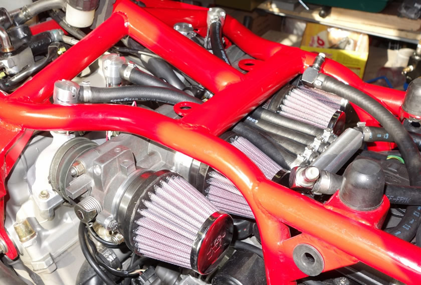
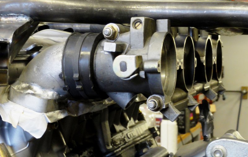
FUEL INJECTION MODIFICATIONS (2013): After the initial Dyno run in 2012 indicated that the overall power was down substantially, I decided it was time to proceed to reloate the Fuel Injectors from underneath the throttle bodies, to the topside, pointing straight down the intake port to the top of the valves, plus install K&N pod filters. The work started April 2013, with welding injector spigots into the manifolds, then devising attachment for the injectors, then making a new fuel rail. All simple when put in one sentance, but the process has proved to be very challenging in every step. There simply is very little room for the injectors, the fuel rails, fuel piping, wiring, throttle cables etc. May 25, 2013 the setup was dynotested, with encrouaging results, up 8 HP from 2012, but power dropped off at 10,000rpm, pointing to top end fuelling issue. Here is the link to the DYNO RUN. The first rework involved installing a new high flow fuel pump (255l/hr) which proved unsuccessful - cavitation causing starvation. The latest modification increased the fuel rail pressure to 4Bar (up from 3Bar), still maintaining the original Bosch fuel pump. This has solved the issue, with acceleration from 7000rpm all the way to redline at 13,200rpm abosolutely astounding. Checking the map with an AFR meter shows the midrange still lean, but top end right on the money. I have some plans to install the stock Brutale headers with 4 into 2 into 4 confirguration. The induction roar at 6500rpm needs to be reduced. Here's the process and pictures of the rework: Finished result- fuel rail behind pod filters with long hose fuel pipes to injector caps.
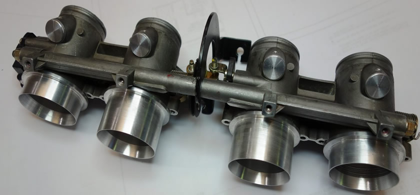
Throttle bodies modified - capped injector mounts, billet adapters for the K&N Pod filters.
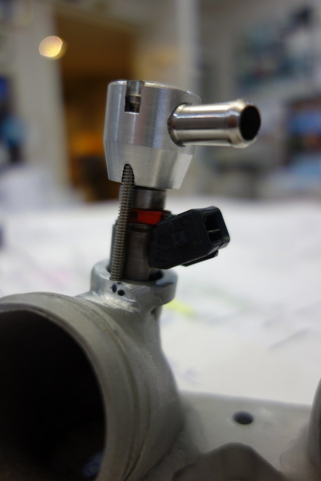
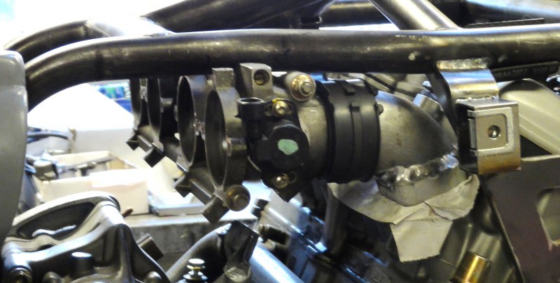
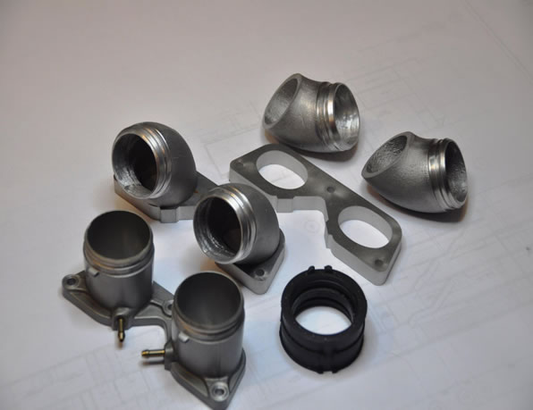
Injector mounted in manifold.
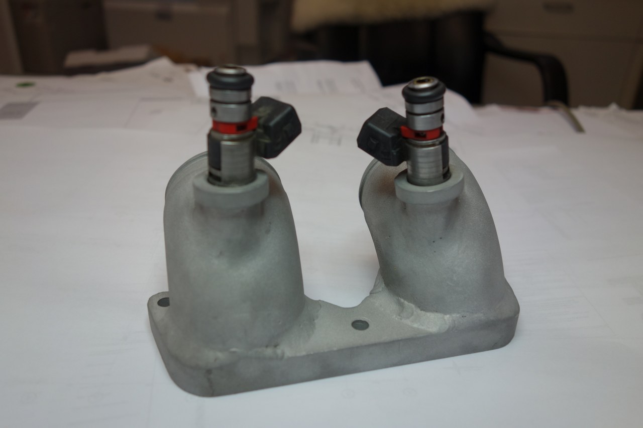
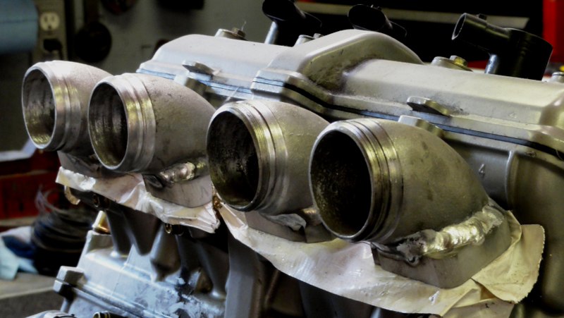
Veiw of welded manifold
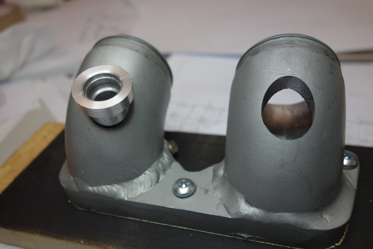
Manifold setup for welding the new injector mounting.
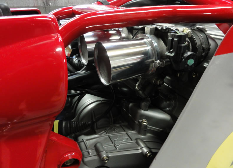
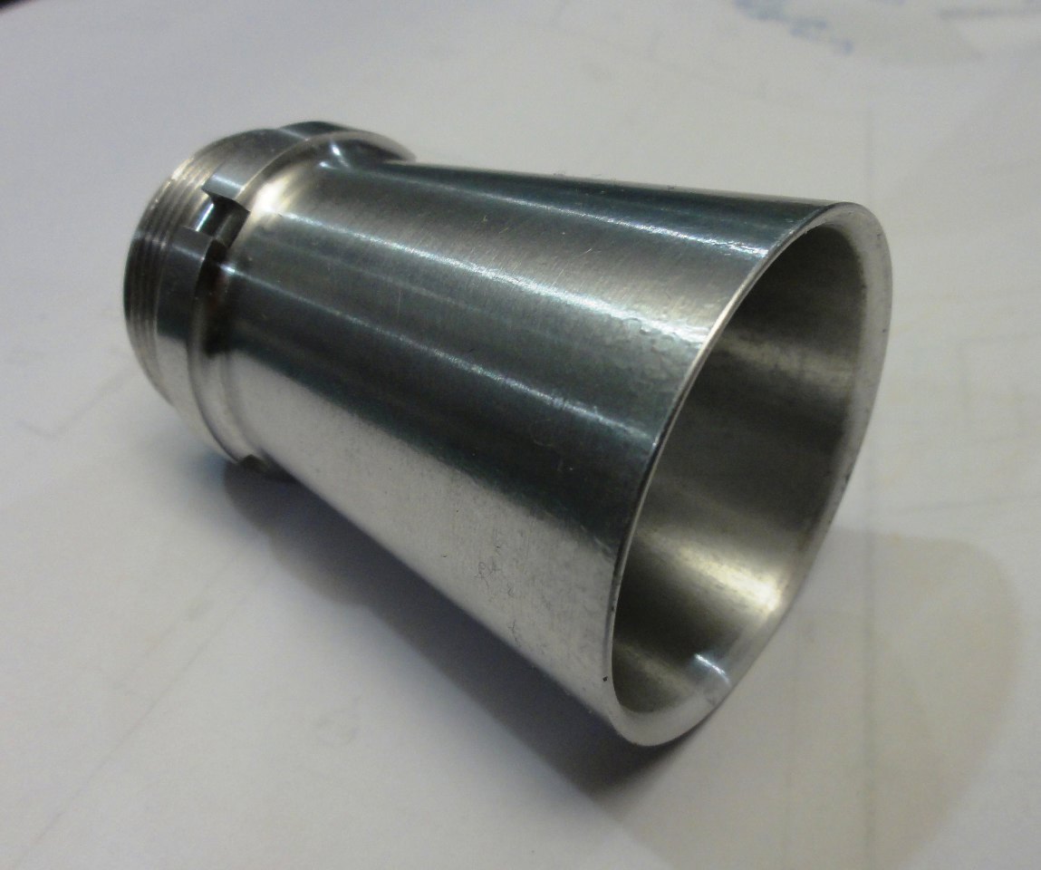
BELOW IS THE 2012 SETUP USED PRIOR TO RELOCATING THE FUEL INJECTORS April 26, 2012 - CNC machined velocity stacks made and installed. I stayed with the typcial straight taper type - 3deg x 2 1/2" long with rounded front lip and a fine stainless steel mesh screen. They are a nice tight fit in the throttle bodies and clear all the wiring and hoses behind the engine.
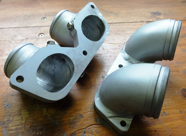
March 18, 2012 - Manifolds were hand blended on the inside to match the base plate and finished on the outside with silver manifold paint. The only issue now with the throttle bodies is making a bracket for the throttle cables. I think I have a solution - it involves splitting the throttle bodies and fabricating a metal bracket. Below is a shot of the type of velocity stack (or trumpet) I plan on machining from 2 1/2" billet aluminum.
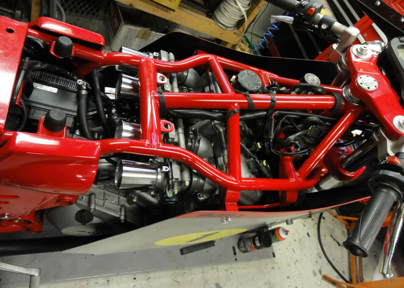
February 22, 2012 It has only taken 7 months to get around to completing the manifolds. After grinding and fitting the elbows to fit a welding jig, Expert TIG welder Maurice completed the aluminum welding of the elbows to the waterjet manifold plate. The throttle body pack now sits nicely under the frame rails. There is at least 1/4" clearance from the frame rails. I will weld 2 tabs on the frame to support the throttle bodies. The manifold welds will be cleaned up and bead blasted for a silver paint finish. I plan on making a set of classic straight velocity stacks used on the race MV's- it should throw a few peolpe off seeing injectors with velocity stacks.
First custom engine parts are underway. In order to squeeze the fuel injectors under tank, it is necessary to modifiy the manifolds with a tight bend. I had my friendly waterjet guy knock up some 1/2" aluminum mounting plates using the original ones as a pattern. I sourced some 2" aluminum elbows from a turbo parts supplier on eBay for $10ea. These have now been cut to lenght and machined for the rubber boot. Final fit and alignment still to go and TIG welding together. I will make up an alignment jig for the welding process so the manifold will match to the injector bodies.
|